...........

Image and video hosting by TinyPic

Pages

Monday, 13 June 2011

Bench Amplifier


Description:
A small 325mW amplifier with a voltage gain of 200 that can be used as a bench amplifier, signal tracer or used to amplify the output from personal radios, etc.
Circuit diagram

Notes:
The circuit is based on the National Semiconductor LM386 amplifier. In the diagram above, the LM386 forms a complete non-inverting amplifier with voltage gain of x200.
A datasheet in PDF format can be downloaded from the National Semiconductor website. The IC is available in an 8 pin DIL package and several versions are available; the LM386N-1 which has 325mW output into an 8 ohm load, the Lm386N-3 which has 700mW output and the LM386N-4 which offers 1000mW output. all versions work in this circuit.
The gain of the Lm386 can be controlled by the capacitor across pins 1 and 8. With the 10u cap shown above, voltage gain is 200, omitting this capacitor and the gain of the amplifier is 20.
The IC works from 4 to 12Volts DC, 12Volt being the maximum recommended value. The internal input impedance of the amplifier is 50K, this is shunted with a 22k log potentiometer so input impedance in this circuit will be lower at about 15k. The input is DC coupled so care must be taken not to amplify any DC from the preceeding circuit, otherwise the loudspeaker may be damaged. A coupling capacitor may included in series with the 22k control to prevent this from happening.
The finished circuit.

Low impedance microphone amplifier


Description
The circuit is a microphone amplifier for use with low impedance (~200 ohm) microphones. It will work with stabilized voltages between 6-30VDC. If you don't build the impedance adapter part with T1, you get a micamp for higher impedance microphones. In this case, you should directly connect the signal to C7.
Schematic diagram


Amplifier of acoustic frequencies with preamplifier


Technical characteristics:
Tendency of catering: 15V
Force of expense: 4,2Wrms in the 4W
Minimal signal of entry: 94mVp-p with preamplifier, 0,65Vp-p without the preamplifier.
Circuit diagram


Three-Level Audio Power Indicator


Battery-operated 3 LED display
Simply connect it to loudspeaker output
Circuit diagram


Audio Perimeter Monitor


Circuit diagram

Notes:
Using a single cable such as speaker wire or doorbell cable, this circuit can be remotely positioned, for
example, at the bottom of a garden or garage, and used to detect all sound in that area. The cable can
be buried in a hosepipe or duct and is concealed out of sight. The mic is an ordinary dynamic mic insert
and should be housed in a waterproof enclosure with the rest of the circuit.
The mic output is amplified by the two transistors, the output is fed down the cable via the 220u capacitor.
Here, it has a dual purpose of preventing the DC supply from upsetting the bias of the circuit, and also
allowing the smaller ac audio output to pass down the line. At the power supply, the audio is recovered
by the 10k preset and 220u capacitor. It is used to feed a small audio amplifier (such as the 2watt design)
shown earlier on this site.

FET Audio Mixer


This simple circuit mixes two or more channels into one channel (eg. stereo into mono). The circuit can mix as many or as few channels as you like and consumes very little power. The mixer is shown with two inputs, but you can add as many as you want by just duplicating the "sections" which are clearly visible on the schematic.
Circuit diagram


Portable Microphone Preamplifier


circuit diagram


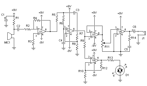
Electronic Stethoscope


Stethoscopes are not only useful for doctors, but home mechanics, exterminators, spying and any number of other uses. Standard stethoscopes provide no amplification which limits their use. This circuit uses op-amps to greatly amplify a standard stethoscope, and includes a low pass filter to remove background noise.
Circuit diagram

Parts:
R1 10K 1/4W Resistor
R2, R3, R9 2.2K 1/4W Resistor
R4 47K 1/4W Resistor
R5, R6, R7 33K 1/4W Resistor
R8 56K 1/4W Resistor
R10 4.7K 1/4W Resistor
R11 2.5K Pot
R12 330K 1/4W Resistor
R13 1K 1/4W Resistor
R14 3.9 Ohm 1/4W Resistor
C1 470uF Electrolytic Capacitor
C2, C3, C4 0.047uF Capacitor
C5 0.1uF Capacitor
C6 1000uF Electrolytic Capacitor
D1 Bi-Colour LED
U1, U2, U3, U4, U5 741 Op-Amp
MIC1 Electret Mic
J1 1/4" Phone Jack
MISC Board, Wire, Sockets for ICs, Knob for pot, Stethoscope, Rubber tube
Notes:
1. MIC1 is an assembly made out of a stethoscope head and electret mic. Cut the head off the stethoscope and use a small piece of rubber tube to join the nipple on the head to the mic.
2. Be careful with the volume, as excess noise level may damage your ears.
3. The + and - 9V may be supplied by two 9V batteries wired in series and tapped at the junction.
4. R11 is the volume control.

Precision Audio Millivoltmeter


Measures 10mV to 50Volt RMS in eight ranges
Simply connect to your Avo-meter set @ 50uA range


Electronics Attenuator


circuit diagram

Two low voltage, low power zeners are used to control electronically the level of an audio signal. The attenuation range is from 6 to 58dB for an input current from 0.042 to 77 mA corresponding to a control voltage from 2.7 to 7.5V. If control voltage is limited to 5V, the attenuation is around 30dB at a control current of 2mA. This is not an HiFi attenuator but might come useful as a general purpose audio attenuator.

Stereo Tube Amplifier


The circuit is simple, yet is capable of excellent performance. I designed it specifically for use as an amplifier for the digital sound card in my computer. Audio input can be from any two-channel line level device such as a television, CD player, or VCR. It is of the tube type, using only 5 tubes total with no more than about 45 Watts power consumption from the outlet. It uses 3 types of tube 1 5Y3 GT vacuum rectifier, 2 6SF5 GT high-mu triodes, and 2 6K6 power beam amplifiers. These are all full-size octal type tubes which are commonly available today for between $3-5 each.

Mini-box 2W Amplifier


Designed for self-powered 8, 4 & 2 Ohm loudspeakers
Bass-boost switch
Circuit diagram: 


Headphone Amplifier


High Quality unit. No need for a preamplifier.
circuit diagram


Phono Preamplifier


circuit diagram


Speaker Box Audio Amp


Design Philosophy
I did this design after getting a new computer. After buying the processor, monitor, and printer, I wasn't willing to spring for a set of speakers too. After going "soundless", I decided to add speakers. Of course, this was the perfect excuse warm up the soldering iron to try out a new design. This original design is a variation on a well-known design, examples of which can be found in a great many texts. My variation was to add a second differential stage to replace the usual common emitter-plus-constant current source. Doing so opens up a second inverse feedback path. The signal path being a series connection of the differential amp inverting inputs, and the feedback being the non-inverting inputs. To this end, the constant current source does not include bypass capacitors to render it a DC-only stage. The other feedback path is the usual one: output to the non-inverting input of the first differential stage. The idea is to add lots of inverse feedback in order to linearize the output transistors, as the non-linearity of these devices makes them rather poor analog amplifiers.

Amplifier Timer


Turns-off your amplifier when idle for 15 minutes
Fed by amplifier tape-output
Circuit diagram


3 Line Mixer


This project is a 3 or more lines mixer. For more than 3 inputs you can repeat the input parts (P=10K R=22K). It powered with 9Vdc.

22 Watt Audio Amplifier


The 22 watt amp is easy to build, and very inexpensive. The circuit can be used as a booster in a car audio system, an amp for satellite speakers in a surround sound or home theater system, or as an amp for computer speakers. The circuit is quite compact and uses only about 60 watts. The circuit is not mine, it came from Popular Electronics.
Circuit diagram


Amplified Ear


circuit diagram


Guitar Amplifier


10W Old-Style ultra-compact Combo
Two inputs - Overdrive - Treble-enhancement
Circuit diagrams: