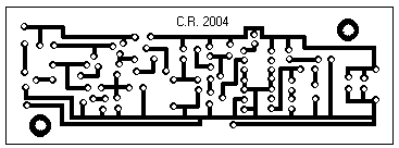
...........

Image and video hosting by TinyPic

Pages

Monday, 13 June 2011

18W Audio Amplifier


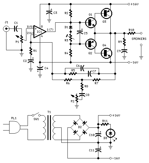
circuit diagram

Amplifier parts:
P1 = 22K Log.Potentiometer (Dual-gang for stereo)
R1 = 1K 1/4W Resistor
R2 = 4K7 1/4W Resistor
R3 = 100R 1/4W Resistor
R4 = 4K7 1/4W Resistor
R5 = 82K 1/4W Resistor
R6 = 10R 1/2W Resistor
R7 = R22 4W Resistor (wire wound)
R8 = 1K 1/2W Trimmer Cermet (optional)
C1 = 470nF 63V Polyester Capacitor
C2,C5 = 100uF 3V Tantalum bead Capacitors
C3,C4 = 470uF 25V Electrolytic Capacitors
C6 = 100nF 63V Polyester Capacitor
D1 = 1N4148 75V 150mA Diode
IC1 = TLE2141C Low noise,high voltage,high slew-rate Op-amp
Q1 = BC182 50V 100mA NPN Transistor
Q2 = BC212 50V 100mA PNP Transistor
Q3 = TIP42A 60V 6A PNP Transistor
Q4 = TIP41A 60V 6A NPN Transistor
J1 RCA audio input socket
Power supply parts:
R9 = 2K2 1/4W Resistor
C7,C8 = 4700uF 25V Electrolytic Capacitors
D2 100V 4A Diode bridge
D3 5mm. Red LED
T1 220V Primary, 15 + 15V Secondary 50VA Mains transformer
PL1 Male Mains plug
SW1 SPST Mains switch
Notes:
Can be directly connected to CD players, tuners and tape recorders.
Don't exceed 23 + 23V supply.
Q3 and Q4 must be mounted on heat sink.
D1 must be in thermal contact with Q1.
Quiescent current (best measured with an Avo-meter in series with Q3 Emitter) is not critical.
Adjust R3 to read a current between 20 to 30 mA with no input signal.
To facilitate current setting add R8 (optional).
A correct grounding is very important to eliminate hum and ground loops. Connect in the same point the ground sides of J1, P1, C2, C3 &C4. Connect C6 at the output ground.
Then connect separately the input and output grounds at the power supply ground.
Technical data:
Output power: 18 Watt RMS @ 8 Ohm (1KHz sine wave)
Sensitivity: 150mV input for 18W output
Frequency response: 30Hz to 20KHz -1dB
Total harmonic distortion @ 1KHz: 0.1W 0.02% 1W 0.01% 5W 0.01% 10W 0.03%
Total harmonic distortion @10KHz: 0.1W 0.04% 1W 0.05% 5W 0.06% 10W 0.15%
Unconditionally stable on capacitive loads

60W Bass Amplifier


Low-cut and Bass controls
Output power: 40W on 8 Ohm and 60W on 4 Ohm loads
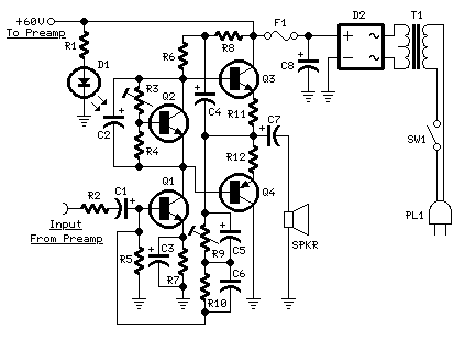
Amplifier circuit diagram:

Amplifier parts:
R1 6K8 1W Resistor
R2,R4 470R 1/4W Resistors
R3 2K 1/2W Trimmer Cermet
R5,R6 4K7 1/2W Resistors
R7 220R 1/2W Resistor
R8 2K2 1/2W Resistor
R9 50K 1/2W Trimmer Cermet
R10 68K 1/4W Resistor
R11,R12 R47 4W Wirewound Resistors
C1,C2,C4,C5 47µF 63V Electrolytic Capacitors
C3 100µF 25V Electrolytic Capacitor
C6 33pF 63V Ceramic Capacitor
C7 1000µF 50V Electrolytic Capacitor
C8 2200µF 63V Electrolytic Capacitor (See Notes)
D1 LED Any type and color
D2 Diode bridge 200V 6A
Q1,Q2 BD139 80V 1.5A NPN Transistors
Q3 MJ11016 120V 30A NPN Darlington Transistor (See Notes)
Q4 MJ11015 120V 30A PNP Darlington Transistor (See Notes)
SW1 SPST Mains switch
F1 4A Fuse with socket
T1 220V Primary, 48-50V Secondary 75 to 150VA Mains transformer
PL1 Male Mains plug
SPKR One or more speakers wired in series or in parallel. Total resulting impedance: 8 or 4 Ohm. Minimum power handling: 75W
Preamplifier circuit diagram:
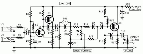
Preamplifier parts:
P1 10K Linear Potentiometer
P2 10K Log. Potentiometer
R1,R2 68K 1/4W Resistors
R3 680K 1/4W Resistor
R4 220K 1/4W Resistor
R5 33K 1/4W Resistor
R6 2K2 1/4W Resistor
R7 5K6 1/4W Resistor
R8,R18 330R 1/4W Resistors
R9 47K 1/4W Resistor
R10 18K 1/4W Resistor
R11 4K7 1/4W Resistor
R12 1K 1/4W Resistor
R13 1K5 1/4W Resistor
R14,R15,R16 100K 1/4W Resistors
R17 10K 1/4W Resistor
C1,C4,C8,C9,C10 10µF 63V Electrolytic Capacitors
C2 47µF 63V Electrolytic Capacitor
C3 47pF 63V Ceramic Capacitor
C5 220nF 63V Polyester Capacitor
C6 470nF 63V Polyester Capacitor
C7 100nF 63V Polyester Capacitor
C11 220µF 63V Electrolytic Capacitor
Q1,Q3 BC546 65V 100mA NPN Transistors
Q2 BC556 65V 100mA PNP Transistor
J1,J2 6.3mm. Mono Jack sockets
SW1 SPST Switch
Circuit description:
This design adopts a well established circuit topology for the power amplifier, using a single-rail supply of about 60V and capacitor-coupling for the speaker(s). The advantages for a guitar amplifier are the very simple circuitry, even for comparatively high power outputs, and a certain built-in degree of loudspeaker protection, due to capacitor C8, preventing the voltage supply to be conveyed into loudspeakers in case of output transistors' failure.
The preamp is powered by the same 60V rails as the power amplifier, allowing to implement a two-transistors gain-block capable of delivering about 20V RMS output. This provides a very high input overload capability.
Technical data:
Sensitivity:
70mV input for 40W 8 Ohm output
63mV input for 60W 4 Ohm output
Frequency response:
50Hz to 20KHz -0.5dB; -1.5dB @ 40Hz; -3.5dB @ 30Hz
Total harmonic distortion @ 1KHz and 8 Ohm load:
Below 0.1% up to 10W; 0.2% @ 30W
Total harmonic distortion @ 10KHz and 8 Ohm load:
Below 0.15% up to 10W; 0.3% @ 30W
Total harmonic distortion @ 1KHz and 4 Ohm load:
Below 0.18% up to 10W; 0.4% @ 60W
Total harmonic distortion @ 10KHz and 4 Ohm load:
Below 0.3% up to 10W; 0.6% @ 60W
Bass control:
Fully clockwise = +13.7dB @ 100Hz; -23dB @ 10KHz
Center position = -4.5dB @ 100Hz
Fully counterclockwise = -12.5dB @ 100Hz; +0.7dB @ 1KHz and 10KHz
Low-cut switch:
-1.5dB @ 300Hz; -2.5dB @ 200Hz; -4.4dB @ 100Hz; -10dB @ 50Hz
Notes:
The value listed for C8 is the minimum suggested value. A 3300µF capacitor or two 2200µF capacitors wired in parallel would be a better choice.
The Darlington transistor types listed could be too oversized for such a design. You can substitute them with MJ11014 (Q3) and MJ11013 (Q4) or TIP142 (Q3) and TIP147 (Q4).
T1 transformer can be also a 24 + 24V or 25 + 25V type (i.e. 48V or 50V center tapped). Obviously, the center-tap must be left unconnected.
SW1 switch inserts the Low-cut feature when open.
In all cases where Darlington transistors are used as the output devices it is essential that the sensing transistor (Q2) should be in as close thermal contact with the output transistors as possible. Therefore a TO126-case transistor type was chosen for easy bolting on the heatsink, very close to the output pair.
R9 must be trimmed in order to measure about half the voltage supply from the positive lead of C7 and ground. A better setting can be done using an oscilloscope, in order to obtain a symmetrical clipping of the output waveform at maximum output power.
To set quiescent current, remove temporarily the Fuse F1 and insert the probes of an Avo-meter in the two leads of the fuse holder.
Set the volume control to the minimum and Trimmer R3 to its minimum resistance.
Power-on the circuit and adjust R3 to read a current drawing of about 30 to 35mA.
Wait about 15 minutes, watch if the current is varying and readjust if necessary.

Ultrasonic Dog Whistle


It's well known that many animals are particularly sensitive to high-frequency sounds that humans can't hear. Many commercial pest repellers based on this principle are available, most of them operating in the range of 30 to 50 kHz. My aim was, however, to design a slightly different and somewhat more powerful audio frequency/ultrasonic sound generator that could be used to train dogs. Just imagine the possibilities - you could make your pet think twice before barking again in the middle of the night or even subdue hostile dogs (and I guess burglars would love that!). From what I've read, dogs and other mammals of similar size behave much differently than insects. They tend to respond best to frequencies between 15 and 25 kHz and the older ones are less susceptible to higher tones. This means that an ordinary pest repeller won't work simply because dogs can't hear it. Therefore, I decided to construct a new circuit (based on the venerable 555, of course) with a variable pitch and a relatively loud 82 dB miniature piezo beeper. The circuit is very simple and can be easily assembled in half an hour. Most of the components are not really critical, but you should keep in mind that other values will probably change the operating frequency. Potentiometer determines the pitch: higher resistance means lower frequency. Since different dogs react to different frequencies, you'll probably have to experiment a bit to get the most out of this tiny circuit. The circuit is shown below:
Circuit diagram

Despite the simplicity of the circuit, there is one little thing. The 10nF (.01) capacitor is critical as it, too, determines the frequency. Most ceramic caps are highly unstable and 20% tolerance is not unusual at all. Higher capacitance means lower frequency and vice-versa. For proper alignment and adjustment, an oscilloscope would be necessary. Since I don't have one, I used Winscope. Although it's limited to only 22 kHz, that's just enough to see how this circuit works. There is no need to etch a PCB for this project, perf board will do. Test the circuit to see how it responds at different frequencies. A 4k7 potentiometer in conjunction with a 10nF (or slightly bigger) capacitor gives some 11 to 22kHz, which should do just fine. Install the circuit in a small plastic box and if you want to, you can add a LED pilot light. Power consumption is very small and a 9V battery should last a long time. Possible further experimentation: I'm working on an amplified version of the whistle to get a louder beep. All attempts so far haven't been successful as high frequency performance tends to drop dramatically with the 555. Perhaps I could use a frequency doubler circuit - I just don't know and I've run out of ideas. One other slightly more advanced project could be a simple "anti-bark" device with a sound-triggered (clap) switch that sets off the ultrasonic buzzer as soon as your dog starts to bark.

10W Audio Amplifier with Bass-boost


circuit diagram

Parts:
P1 22K Log.Potentiometer (Dual-gang for stereo)
P2 100K Log.Potentiometer (Dual-gang for stereo)
R1 820R 1/4W Resistor
R2,R4,R8 4K7 1/4W Resistors
R3 500R 1/2W Trimmer Cermet
R5 82K 1/4W Resistor
R6,R7 47K 1/4W Resistors
R9 10R 1/2W Resistor
R10 R22 4W Resistor (wirewound)
C1,C8 470nF 63V Polyester Capacitor
C2,C5 100uF 25V Electrolytic Capacitors
C3,C4 470uF 25V Electrolytic Capacitors
C6 47pF 63V Ceramic or Polystyrene Capacitor
C7 10nF 63V Polyester Capacitor
C9 100nF 63V Polyester Capacitor
D1 1N4148 75V 150mA Diode
IC1 NE5532 Low noise Dual Op-amp
Q1 BC547B 45V 100mA NPN Transistor
Q2 BC557B 45V 100mA PNP Transistor
Q3 TIP42A 60V 6A PNP Transistor
Q4 TIP41A 60V 6A NPN Transistor
J1 RCA audio input socket
Power supply parts:
R11 1K5 1/4W Resistor
C10,C11 4700uF 25V Electrolytic Capacitors
D2 100V 4A Diode bridge
D3 5mm. Red LED
T1 220V Primary, 12 + 12V Secondary 24-30VA Mains transformer
PL1 Male Mains plug
SW1 SPST Mains switch
Comments:
This design is based on the 18 Watt Audio Amplifier, and was developed mainly to satisfy the requests of correspondents unable to locate the TLE2141C chip. It uses the widespread NE5532 Dual IC but, obviously, its power output will be comprised in the 9.5 - 11.5W range, as the supply rails cannot exceed ±18V.
As amplifiers of this kind are frequently used to drive small loudspeaker cabinets, the bass frequency range is rather sacrificed. Therefore a bass-boost control was inserted in the feedback loop of the amplifier, in order to overcome this problem without quality losses. The bass lift curve can reach a maximum of +16.4dB @ 50Hz. In any case, even when the bass control is rotated fully counterclockwise, the amplifier frequency response shows a gentle raising curve: +0.8dB @ 400Hz, +4.7dB @ 100Hz and +6dB @ 50Hz (referred to 1KHz).
Notes:
Can be directly connected to CD players, tuners and tape recorders.
Schematic shows left channel only, but C3, C4, IC1 and the power supply are common to both channels.
Numbers in parentheses show IC1 right channel pin connections.
A log type for P2 ensures a more linear regulation of bass-boost.
Don't exceed 18 + 18V supply.
Q3 and Q4 must be mounted on heatsink.
D1 must be in thermal contact with Q1.
Quiescent current (best measured with an Avo-meter in series with Q3 Emitter) is not critical.
Set the volume control to the minimum and R3 to its minimum resistance.
Power-on the circuit and adjust R3 to read a current drawing of about 20 to 25mA.
Wait about 15 minutes, watch if the current is varying and readjust if necessary.
A correct grounding is very important to eliminate hum and ground loops. Connect in the same point the ground sides of J1, P1, C2, C3 &C4. Connect C9 at the output ground.
Then connect separately the input and output grounds at the power supply ground.
Technical data:
Output power: 10 Watt RMS @ 8 Ohm (1KHz sinewave)
Sensitivity: 115 to 180mV input for 10W output (depending on P2 control position)
Frequency response: See Comments above
Total harmonic distortion @ 1KHz: 0.1W 0.009% 1W 0.004% 10W 0.005%
Total harmonic distortion @ 100Hz: 0.1W 0.009% 1W 0.007% 10W 0.012%
Total harmonic distortion @10KHz: 0.1W 0.056% 1W 0.01% 10W 0.018%
Total harmonic distortion @ 100Hz and full boost: 1W 0.015% 10W 0.03%
Max. bass-boost referred to 1KHz: 400Hz = +5dB; 200Hz = +7.3dB; 100Hz = +12dB; 50Hz = +16.4dB; 30Hz = +13.3dB
Unconditionally stable on capacitive loads

High Quality Intercom


Description:
A very high quality intercom, which may also be used for room monitoring.
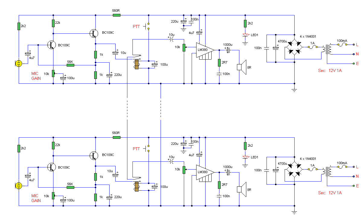
Circuit diagram

Notes:
This circuit consists of two identical intercom units. Each unit contains a power supply, microphone preamplifier, audio amplifier and a Push To Talk (PTT) relay circuit. Only 2 wires are required to connect the units together. Due to the low output impedance of the mic preamp, screened cable is not necessary and ordinary 2 core speaker cable, or bell wire may be used.
The schematic can be broken into 34 parts, power supply, mic preamp, audio amplifierand PTT circuit. The power supply is designed to be left on all the time, which is why no on / off switch is provided. A standard 12 V RMS secondary transformer of 12VA will power the unit. Fuses are provided at the primary input and also secondary, before the rectifier. The 1 A fuse needs to be a slow blow type as it has to handle the peak rectifier current as the power supply electrolytics charge from zero volts.
The microphone amplifier is a 2 transistor direct coupled amplifier. BC108B transistors will work equally well in place of the BC109C transistors. The microphone used is a 3 terminal electret condenser microphone insert. These are popular and require a small current to operate. The preamp is shown in my audio circuit section as well, but has a very high gain and low distortion. The last transistor is biased to around half the supply voltage; this provides the maximum overload margin for loud signals or loud voices. The gain may be adjusted with the 10k preset. Sensitivity is very high, and a ticking clock can easily be heard from the distant loudspeaker.
The amplifier is based on the popular National Semiconductor LM380. A 50 mV input is all thats required to deliver 2W RMS into an 8 ohm loudspeaker. The choice of loudspeaker determines overall sound quality. A small loudspeaker may not produce a lot of bass, I used an old 8 inch radio loudspeaker. The 4.7u capacitor at pin 1 of the LM380 helps filter out any mains hum on the power supply. This can be increased to a 10u capacitor for better power supply rejection ratio.
The push to talk (PTT) circuit is very simple. A SPDT relay is used to switch between mic preamplifier output or loudspeaker input. The normally closed contact is set so that each intercom unit is "listening". The non latching push button switch must be held to talk. The 100u capacitor across the relay has two functions. It prevents the relays back emf from destroying the semiconductors, and also delays the release of the relay. This delay is deliberate, and prevents any last word from being "chopped" off.
Setting Up and Testing:
This circuit does not include a "call" button. This is simply because it is designed to be left on all the time, someone speaking from one unit will be heard in the other, and vice versa. Setup is simple, set to volume to a comfortable level, and adjust the mic preset while speaking with "normal volume" from one meter away. You do not need to be in close contact with the microphone, it will pick up a conversation from anywhere in a room. If the units are a long way away, there is a tendency for the cable to pick up hum, or radio interference. There are various defenses against this. One way is to use a twisted pair cable, each successive turn cancels the interference from the turn before. Another method is to use a small capacitor of say 100n between the common terminal of each relay and ground. This shunts high frequency signals to earth. Another method is to use a low value resistor of about 1k. This will shunt interference and hum, but will shunt the speech signal as well. However as the output impedance of each mic preamp is low, and the speech signals are also low, this will have little effect on speech but reduce interference to an acceptable level.
IC Pinout:
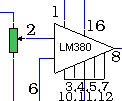
The LM380 pinout viewed from above is shown below on the left. In the schematic, the LM380 has been represented as a triangle, the pins are shown on the right hand diagram. Pins marked "NC" have no connection and are not used.

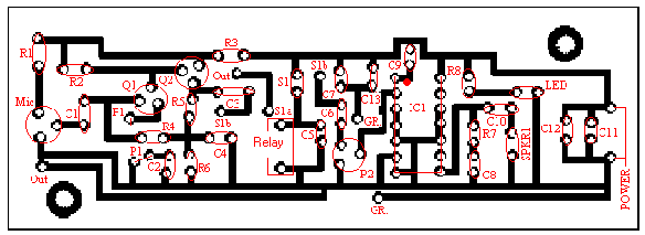
PCB Layout:
Corey Rametta has kindly drafted a PCB layout for this project. First an oversized version to show component placement. Note the tracks on the bottom side, components on the top side.

Below is the actual size version shown track side.