...........

Image and video hosting by TinyPic

Pages

Monday, 13 June 2011

Low pass filter - Subwoofer


The acoustic spectrum is extended by very low frequencies 20Iz and reaches as the 20000Iz in high frequencies. In the low frequencies is degraded the sense of direction. This reason us leads to the utilization speaker for the attribution of very low frequencies. The manufacture that to you we propose distinguishes these frequencies, in order to him we lead to the corresponding amplifier. The acoustic filters are met in various points in the sound systems. The knownest application they are the filters baxandal for regulating tone low and high frequencies and filters crossover where the acoustic region is separated in subareas, in order to it leads the corresponding loudspeakers. The application that to you we propose is a simple filter of region that limits the acoustic region (20-20000Hz) in the region 20-100Hz.
With the manufacture that to you we propose you can make a active filter in order to you lead a loudspeaker of very low frequencies. With this you will place one bigger speaker between the HIFI speakers of you. In order to you have a complete picture of sound you will need also the corresponding amplifier. In the entry of circuit you will connect the two exits of preamplifier or the exit of line of some preamplifier. The circuit of manufacture allocates a exit in order to is led means of circuit of force subwoofer. If for some reason you do not have space in order to you place the third speaker in space of hearing, then you can select smaller speaker. The output will depend from the type of music that you hear. If in deed you have space, then after you make a filter and remain thanked, you can him recommend in your friends or still make other same for your friends.
Circuit diagram

In the form it appears the theoretical circuit of filter. In first glance we see three different circuits that are mainly manufactured round two operational amplifiers. This circuits constitute mixed, amplifier with variable aid and a variable filter. The manufacture end needs a circuit of catering with operational tendency of catering equal with ±12. the operational amplifiers that constitute the active elements for this circuits of are double operational type as the TL082 and NE5532. The operational these amplifiers belong in a family provided with transistor of effect of field IFET in their entries. Each member of family allocates in their circuit bipolar transistor and effect of field. This circuits can function in his high tendency, because that they use transistor of high tendency. Also they have high honor of rhythm of elevation (slew rate), low current of polarization for the entries and are influenced little by the temperature. The operational these amplifiers have breadth of area unity gain bandwidth 3MHz. A other important element for their choice is the big reject of noise, when this exists in the line of catering.
The price of reject is bigger than 80dB, their consumption is small, from 11 until 3 mA. They are internally sold in nutshell with eight pins and allocate two operational amplifiers, In the same line in nutshell 14 pins they incorporate four operational, In the trade they are sold with code TL074, TL084 and TL064, In nutshell with eight pins they are sold operational amplifiers TL061 TL071 kajTL081. In the manufacture we used the TL082 that has two operational. First operational from the TL082 it works as amplifier and mixed for the two channels, In his negative entry he exists one small mixed with two resistances. A potentiometer in this rung determines the aid of circuit. In the point this left winger and the right channel of preamplifier they are added means of two resistances. En continuity the operational strengthens signal with aid made dependent from the price that has the potentiometer.
The place of runner is proportional with the aid of circuit. The second operational amplifier is the filter of manufacture. The filter of is acoustic frequency of second class and he is made with the materials that are round the operational amplifier. The filter of is low passage with variable frequency of cutting off. This frequency can be altered and take prices from very low frequency the 30Hz or still exceed 150Hz. The frequency of cutting off of filter depends from the prices that have the elements of circuit. Altering the values of elements we can have frequency of cutting off 150Iz, 130Iz, J00Iz, 7Ïz, 6Íz even 3Íz, this prices they can be achieved with the simple rotation of double potentiometer. The circuit of filter has been made around one operational' that it has completed TL082 that is double operational amplifier. In the exit of filter we will link the plug of expense where is connected the amplifier. In the exit of circuit is presented, the limited as for the breadth of frequencies, signal that we apply in the entry of circuit.
Manufacture
Parts
R1 = 39 Kohm
R2 = 39 Kohm
R3 = 47 Kohm
R4 = 10 Ohm
R5 = 22 Kohm
R6 = 4,7 Kohm
R7 = 22 Kohm
R8 = 4,7 Kohm
R9 = 10 Ohm
R10 = 220 Ohm
C1 = 39 pF
C2 = 0.1 uF
C3 = 0.1 uF
C4 = 0.2 uF
C5 = 0.4 uF
C6 = 0.1 uF
C7 = 0.1 uF
IC1 = TL064

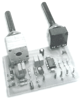
In order to you make the manufacture you will need printed that appears in the form. In this you will place the materials according to the following form. The materials are enough also easy can become certain errors. With few attention however you can him avoid. If they are presented difference malfunctions, you check carefully the circuit. The circuit, as we said, is filter and it should they are used materially good precision and quality, particularly for the capacitors. The capacitors of filters will have tolerance 5%. Of course, the manufacture will also work with material of lower quality, the trial of manufacture can become with acoustic signal of generator We apply the generator in the entry of manufacture and we measure with a voltmeter the tendency in the exit of filter. If we alter the potentiometer and are altered the tendency, then all have well.

Insect Repellant


Circuit diagram

Notes:
Repell those repugnent insects from your Garden this Summer with this insect repellant circuit. Designed by Graham Maynard the circuitry consists of a phase locked loop (CMOS 4047) wired as a 22KHz oscillator. The output is amplified by a pair of complimentary output transistors and drives a Motorola 3.25 inch Piezo. Current drain is around 120mA so an external power supply is recommended.
The piezo used was a standard 85mm square Motorola Horn, Maplin part number WF09K or WF55K. These are rated +/-3dB to 28kHz.

Electronic Stethoscope


Circuit diagram

Circuit Description:
U1a operates as a low-noise microphone preamp. Its gain is only about 3.9 because the high output impedance of the drain of the FET inside the electret microphone causes U1a’s effective input resistor to be about 12.2K. C2 has a fairly high value in order to pass very low frequency (about 20 to 30Hz) heartbeat sounds.
U1b operates as a low-noise Sallen and Key, Butterworth low-pass-filter with a cutoff frequency of about 103Hz. R7 and R8 provide a gain of about 1.6 and allow the use of equal values for C3 and C4 but still producing a sharp Butterworth response. The rolloff rate is 12dB/octave. C3 and C4 can be reduced to 4.7nF to increase the cutoff frequency to 1KHz to hear respiratory or mechanical (automobile engine) sounds.
The U4 circuit is optional and has a gain of 71 to drive the bi-colour LED.
U5 is a 1/4W power amplifier IC with built-in biasing and inputs that are referred to ground. It has a gain of 20. It can drive any type of headphones including low impedance (8 ohms) ones.
Parts
R1 10K 1/4W Resistor
R2 2.2K 1/4W Resistor
R3, R9 Not used
R4 47K 1/4W Resistor
R5, R6, R7 33K 1/4W Resistor
R8 56K 1/4W Resistor
R10 4.7K 1/4W Resistor
R11 2.2K to 10K audio-taper (logarithmic) volume control
R12 330K 1/4W Resistor
R13, R15, R16 1K 1/4W Resistor
R14 3.9 Ohm 1/4W Resistor
C1, C8 470uF/16V Electrolytic Capacitor
C2 4.7uF/16V Electrolytic Capacitor
C3, C4 0.047uF/50V Metalized plastic-film Capacitor
C5 0.1uF/50V Ceramic disc Capacitor
C6, C7 1000uF/16V Electrolytic Capacitor
U1 TL072 Low-noise, dual opamp
U2, U3 Not used
U4 741 opamp
U5 LM386 1/4W power amp
MIC Two-wire Electret Microphone
J1 1/8" Stereo Headphones Jack
LED Red/green 2-wire LED
Batt1, Batt2 9V Alkaline Battery
SW 2-pole, single throw Power Switch
Misc. Stethoscope head or jar lid, Rubber Sleeve for microphone.
Assembly:
1) Assemble the circuit using Veroboard (stripboard) or a PCB.
2) Use a shielded cable for the microphone as shown on the schematic.
3) Fasten the microphone to the stethoscope head with a rubber isolating sleeve or use a short piece of rubber tubing on its nipple. A thick jar lid can be used as a stethoscope head. The microphone must be spaced away from the skin but the stethoscope head must be pressed to the skin, sealing the microphone from background noises and avoiding acoustical feedback with your headphones.
4) The microphone/stethoscope head must not be moved while listening to heartbeats to avoid friction noises.
5) Protect your hearing. Keep the microphone away from your headphones to avoid acoustical feedback.
Download this project in .doc format


Circuit Description:
This is a 100 watt basic power amp that was designed to be (relatively) easy to build at a reasonable cost. It has better performance (read: musical quality) than the standard STK module amps that are used in practically every mass market stereo receiver manufactured today. When I originally built this thing, it was because I needed a 100 WPC amp and didn't want to spend any money. So I designed around parts I had in the shop.
The design is pretty much a standard one, and I'm sure there are commercial units out there that are similar. To my knowlwdge, it is not an exact copy of any commercial unit, nor am I aware of any patents on the topology. To experienced builders: I realize that many improvements and refinements can be made, but the idea was to keep it simple, and should be do-able by anyone who can make a circuit board and has the patience not to do a sloppy job.
The input stage is an LF351 op amp which provides most of the open loop gain as well as stabilizes the quiescent dc voltage. This feeds a level shift stage which references the voltage swing to the (-) rail. The transconductance stage is a darlington, to improve high-frerqency linearity. The 2SC2344 by itself has a rather large collector-base capacitance which is voltage dependent. The MPSA42 presents this with a low-z and has a C(ob) of only a few pf that is effectively swamped by the 33pF pole-splitting cap. The stage is supplied by the 2SA1011 active load (current source) which is about 20 ma. The current to the stage is limited by the 2N3094 to about 70 ma under worst case.
The output is a full complementary darlington with paralleled outputs. Although you could "get away with" only one if only 8 ohm easy-to-drive loads are used, this is not recommended. The use of parallel devices increases the ability to drive reactive loads (which can pull a significant current while the voltage waveform crosses zero and puts a high voltage and a high curent across the transistor simultaneously), gives the amp a higher damping factor, and reduces the maximum current each transistor has to supply to peaks (remember, the gain of a power transistor drops as the current increases).
Compensation is two-pole and one zero. The op-amp's pole and the pole generated by the 33pf cap and the 470 ohm bias resistor of the MPSA42 dominate. (the 33pF gets multiplied by the stage gain.) The 22 pf feedback capacitor provides lead compensation, and is taken from the output of the tranconductance stage rather than the output itself. In this way, the phase lag introduced by the output transistors is not seen by the high-frequency feedback. This intorduces a closed-loop pole which limits the high-frequency response. The two compensation capacitors must be type 1 creamic (NPO) or silver mica - with ZERO voltage coefficient.
The amp was designed to run 2 channels off a +/- 55 volt unregulated supply, reducing to +/- 48 volts under full load. It used a 40-0-40 volt, 5 amp toroid transformer, a bridge rectifier, and 10,000 uf of filter cap per side. If a standard EI transformer is used, a 6-amp rated unit should be used. With this power supply, it produces 100 watts continuous, both channels driven into 8 ohms resistive with no clipping. Dynamic headroom is about a db and a half. For more headroom, unloaded voltages to +/- 62 volts can be used with no circuit modification.
By the way, the schematic is in Postscript.
Limitations:
With no modifications the amp will drive 4-ohm speaker systems with no current limiting. The short-circuit current limit is set to about 4.5 amps peak, which will handle conventional speaker loads.(It will, of course, produce higher peak currents as the output voltage swing approaches the rail.) If you are going to be running some of those high-end speakers with impedance minima of half an ohm, or that stay reactive throughout most of the audio band ( ie, 0.5 +j3.2 ohms) you will probably already own a better amp than this. If the higher-power Motorola power transistors are used, it will drive a 2-ohm resistive load without problems (except heat).
I have never heard any slew-induced distortion on this amp with a CD player's band-limited (22KHz) signal. I suppose that real high-end freaks could pick it to pieces by hitting it with a TTL square wave mixed with a 19KHz stereo pilot tone and crank it up. I guarantee that there will be spurs all over the spectrum, but who listens to that?
Possible Modifications: (What if I want mo' power???)
The Toshiba output transistors (2SD424/2SB554 pair) shoud not be used with supply voltages above +/-60 volts. If you plan on cranking it up, use more in parallel or use the 250 watt Motorola pairs (MJ15024/MJ15025). If very low impedances are expected, raise the bias in the transconductance stage to give more base drive to the output darlingtons or add another current gain stage. Higher-Beta (and faster) power transistors can't handle reactive loads worth a crap. Don't substitute high-fT parts unless you are sure they have adequate second-breakdown capability.
The NE5532 op-amp can be used in the input stage. If more than one are used off the +/-15 volt shunt regulators (balanced ins, anti-slew Bessel filters, etc.) the 2.7K dropping resistors may need to be reduced to say, 1.8K ohm to maintain regulation. The 2.7K resistors will allow up to 4 LF351 type op amps off the regulator (I used a quad 347 for balanced inputs to avoid hum in a DJ setup).
Construction tips:
The output transistors and thermal compensator (2SC1567) will need to be mounted on a common heat sink - a finned unit measuring 5 in. high by 8 in. wide with 1.25 in fins should do nicely for one channel. (They look nice if you make the sides of the case out of them). Most normal applications won't require more cooling than this. The reason the 2SC1567 was chosen for the output bias regulator is because it is fully insulated - the ECG version will require additional mounting hardware. TO-3 hardware for the outputs is cheap and easy to get.
The driver transistors and voltage amps (2SC3344/2SA1011 pairs) will all require heatsinking as well. Individual TO-220 heat sinks on the circuit board will suffice - the voltage amps dissipate about 1.4 watts each. A common piece of 1/8 in. thick 1 in. wide X 4in. long angle aluminum will suffice for all 4 on each channel, but bear in mind that it must be oriented to take advantage of natural convection, and the transistors must be insualted.
Keep the imput grounds separate from everything else, and return them at ONE point. Failure to do so WILL result in high distortion (5% or so), or even oscillation.
The output stage bias should be set to about 25 milliamps in the output transistors. This value takes a while to stabilize, and you may have to monitor it over an hour or so during initial setup. To measure it, measure the voltage across the emitter resistor and use Ohm's law. This way, you can check the current sharing in the parallel output transistors at the same time and change them if there is a serious discrepancy. With parts of the same date code, they should not be off by more than 10% after it has warmed up. Higher output stage biases can be used, but it takes more care in setting it. If you want an idle current of more than 50 milliamps per side, increase the value of the emitter resistors.
Initial Checkout:
DO NOT just plug something like this in! A seemingly insignificant error can set your house on fire! (As well as blow out $30 worth of transistors in a microsecond.) A variac will work in theory, but the amp may latch to the rail if the supply drops too low. I suggest the use of a ballast resistor - a 60 to 100 watt light bulb in series with the AC mains. You get a bright flash when the caps charge, and then it goes (almost) out as the idling supply current reaches its nominal low value. The amplifier will then work normally at low volumes. If the amp draws too much current for whatever reason, the lightbulb will glow brightly, increase resistance, and limit the power to the circuit. Usually, there will either be a mis-wire (use your DMM) or oscillation (will show up on a scope or RF power measuring device). If the bulb goes dim-bright-dim-bright... then the amp is marginally stable and the grounding layout should be checked. Compensation capacitor values may need to be adjusted if any significant changes were made. Mine is stable the way it is.
Additional Notes:
The schematic is in postcript, so it should just be able to be printed out. The emitters of the transistors are labelled by an "e". I was too lazy to put arrows on the transistor symbols - and I've been using it that way for over a year now.
Trouble finding parts? MCM (1-800-543-4330) has all the transistors. Total cost for a stereo version should be between $150 and $250, depending on what kind of bargains you can find on the case, transformer, and heatsinks. If you have to pay "list" for everything, it will likely cost about $1000 to build.
The information included herin is provided as-is, with no warranties express or implied. No resposibility on the part of the author is assumed for the technical accuracy of the information given herein or the use or mis-use of said information.
The equipment described in this article was designed, fabricated, and tested on my own personal time using my own personal resources.
Click HERE to get the pdf circuit diagram.

2N3055 Power Amplifier


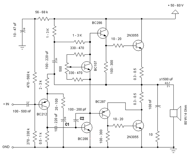
Simple and low cost. The optimal supply voltage is around 50V, but this amp work from 30 to 60V. The maximal input voltage is around 0.8 - 1V. As you can see, in this design the components have a big tolerance, so you can build it almost of the components, which you find at home. The and transistors can be any NPN type power transistor, but do not use Darlington types... The output power is around 60W.
Some comments:
- capacitor C1 regulates the low frequencies (bass), as the capacitance grows, the low frequncies are getting louder.
- capacitor C2 regulates the higher frequencies (treble), as the capacitance grows, the higher frequencies are getting quiter.
- this is a class B amplifier, this means, that a current must flow through the end transistors, even if there is no signal on the input. This current can be regulated with the 500ohm; trimmer resistor. As this current incrases, the sound of the amplifier gets better, but the end transistors are more heating. But if this current decrases, the transistors are not heating so much, but the sound gets worse...
Circuit diagram